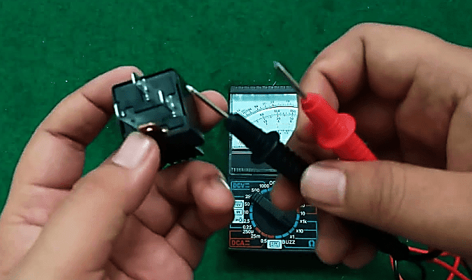
How to test a relay?
The main function of relay is as an electromagnetic switch that will work when the relay's coil is energized. This component is widely used in automotive electrical components. Apart from an electromagnetic switch, relays are also can be used as a safety device so that the switch (horn swicth, light switch, etc) can be more durable and its avoid from fires due to excess electric current.
As an electrical components, relay can be broken anytime. Mostly, when there are any problems in electrical components malfunctions such as dead, broken or damaged. On this case, relay is also need to be checked to ensure that the electrical lines and wirings are in good condition.
So, how do you test a relay with a multimeter? Well, in this article, i will share tips on how to test a relay with a multimeter. But beforehand, here are some tools and materials that need to be prepared before carrying out a relay tests.
- Digital Multimeter (DMM)
- Replacement relay
- Jumper wires
- Battery
If all tools are ready, then the next step to test a relay is to determine the relay terminals. See the step by step on how to test a relay below...
I. Determine the relay terminals and it's function
The first step on how to test a relay is to determine the relay terminals and it's function. Mostly of automotive relays have relay scheme or diagram were printed on their body or case. The relay's diagram will show the function of each number were also printed near the relay terminals.
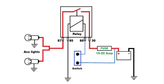
Generally, automotive relays had 4 and 5 terminals were indicated by number 30, 85, 86, 87, and 87a (for relay with 5 terminals). See the example image below for relay with 4 terminals and 5 terminals.
For most automotive relays with 4 terminals are Normally Open type which is mean that the switch is always open (not connected) when the relay is not energized. This switch is identified with terminal 30 and terminal 87.
For relays with 5 terminals, this can be a Normally Closed type and or Normally Open type. It is depending on which terminal number that you used for the electric load. For example, if you put the electric load on terminal 87a, then you use a Normally Closed type. But if you put the load on terminal 87, then you use a Normally Open type.
Here is general relays terminals connected to
- 30 , connected to power source (battery)
- 85 and 86 are coil, connected to power or ground controler circuit such as horn switch or headlight switch.
- 87 and 87a , connected to electric load for example for horn or headlight.
II . Turn the Digital multimeter to ohm meter for measurement
Turn on the digital multimeter to ohm meter for measurement. Connect the red lead (+) and the black lead (-) of multimeter to do zero adjustment before we test a relay. When the result displays zero (0) ohm, it means that the connection is connected. When the result display unlimited (~), it means the connections lost or broken.
III. Measure terminals 85 and 86
Terminal 85 and 86 are coil connected, generally they not use polarity so you can put the multimeter leads vice versa. Put the leads wire of multimeter on terminal 85 and 86 and see the result.
- If terminal 85 and 86 are connected (show zero ohm), then the relay's coil is in good conditions
- If terminal 85 and 86 are disconnected (show unlimited), then the relay's coil is broken. It means the relay is bad and need replacement.
Read more:
IV. Measure terminals 30 and 87
Terminal 30 and 87 are switch connected. But to measure this terminals we need to look at the relay's diagram. There are different result for relays with 4 terminals and relays with 5 terminals.
As we mentioned before, relays with 4 terminals are Normally open type. So, when we connect the multimeter leads to those terminals, the multimeter measurement should not be connected. To make sure that the switch is in good conditions, we need to energizing the relay's coil by putting some electric power source to the terminal 85 and 86 using battery.
With the image above, when the switch 1 is connected, the relay's coil will energizing and produce magnetic force. The magnetic force is attract the switch between terminal 30 and terminal 87. At this state, the multimeter should be connected (the displays shows zero ohm).
For relays with 5 terminals, the measures are depends from where the electric load is placed. If using terminal 87 then this should normally open, and if using terminal 87a, then its normally closed. Here is a TABEL recap for the relay test
| RELAY | Switch 1 | Measured Terminals | GOOD |
|---|---|---|---|
| 4 Terminals | 85 and 86 | Connected | |
| ON | 30 and 87 | Connected | |
| OFF | 30 and 87 | Disconnected | |
| 5 Terminals | 85 and 86 | Connected | |
| Normally Open (87a not use) | ON | 30 and 87 | Connected |
| OFF | 30 and 87 | Disconnected | |
| 5 Terminals | 85 and 86 | Connected | |
| Normally Closed (87 not use) | ON | 30 and 87a | Disconnected |
| OFF | 30 and 87a | Connected | |


