How relay works in car?
For most modern car there always use relays in every electric diagram such as horn, headlamps, engine power circuit, even for an air conditioner systems. Relays are switches that open and close circuits electronically.
It is use electromagnetic force were energized with coil to control the opening or closing switch contacts in the other circuit. Yes, relays control one electrical circuit by opening and closing switch contacts in another circuit.
There are two types of relays based on the position of the switch contacts, Normally Open (NO) and Normally Closed (NC). Normally Open means that there is an open switch contact when the relay is not energized. Normally Closed means that there is a closed switch contact when the relay is not energized.
The NO type is normally disconnected the electricity flow, while the NC type is normally connected the circuit so the electric can flow through the circuit. Applying electrical current to the coil will change the state of their switch contact.
Apart from NO and NC, relays are also differentiated based on the type of switch, such as SPST (single pole single throw), SPDT (Single Pole Double Throw), DPST (Double Pole Single Throw), and DPDT (Double Pole Double Throw). But on todays article, we just inform you on how relay works in car.
Relay parts and function
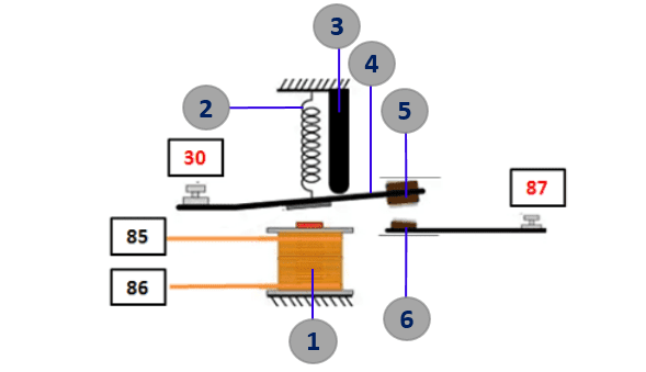
To better understanding on how relay works, the first thing that we have to know is the relay parts and function. As we mentioned before, there are 4 types relay based on the switch type, so to make it simple, we'll give you an example of Normally Open relay with single pole single throw (SPST) type. Below is the example of Normally Open (NO) relay with simple terms
- Coil : Coil is used to energizing magnetic field (electromagnetic) to attract the armature so the moveable contact and fixed contact can connect each other. At the end of coil's cable, its connected to terminals 85 or 86.
- Spring : Spring is used to pull the armature back to its position when the coil end its magnetic field.
- Stopper : Stoper is used to keep the distance between moveable contact and fixed contact are in tolerable distance.
- Armature : Armature is an arm that hold the moveable contact at its end. Armature have a pivot and its connected to the spring. When the coil energizing magnetic field, the armature attracted to the coil. From the image above, the armature is connected to the terminal 30
- Moveable contact : Moveable contact is conected to the armature, this is the contact point were the electric can flow. In the diagram, this contact point is draw as a switch.
- Fixed contact : Fixed contact is a contact point which contact with moveable contact and stay with the base. Fixed contact can't move like moveable contact. It is connected to the terminal 87.
How relay works
Before we learn on how relay works, look at the simple relay circuit diagram for horn below. It is use a normaly open relay and have four terminals such as 30, 85, 86, and 87. Generally, terminal 30 connected to the power source (battery), terminal 87 connected to the electric load (such as horn, motor, lamps, etc), meanwhile terminal 85 and 86 are connected to the switch.
Here is how relay works :
- When we push the horn switch, the electricity will flow from the battery > terminal 85 > coil > terminal 86 > horn switch > ground. At this state, the coil will energizing magnetic field.
- With magnetic field on, the coil will attract the switch so the moveable contact and fixed contact are connected
- At the same time, the electricity will flow from battery > fuse > terminal 30 > switch > terminal 87 > horn > ground. At this state, the horn will sound.
- When we release the horn button switch, the magnetic field on the coil will lost and the spring pullback the armature so the electric flow to the horn will stop. At this state the horn are no sound.
The simple things to remember on how relay works is when the coil is electrified, then the coil will be a magnet (electromagnet). The magnet will attract the switch to connected so that the circuit will be on and activated the electric load.


