How an alternator works?
The alternator works based on the electromagnetic work principle. The principle of electromagnetic is simple: when a magnet (with magnetic field) moves forward and backward inside the coil, the electric current energy will generate. See the animated electromagnetic works principle below
The animated image above shows that the orange lines around the magnet (which is a magnetic field) cut off the coil when the magnet moves forward and backward. As the magnetic field cuts the coil, the electric current generates. And from the image above, the electric current makes the lights turn ON and OFF.
The alternator used the same principle as the example images above, but it has more complicated in its application. Why is it more complicated? One of many reasons is the alternator generates an alternating current (AC) which cannot be used in most cars' electric systems and components.
For the reasons, the first step to understand how the alternator works is to know the alternator diagram, parts, and function. See the alternator diagram, parts, and function below
I. Alternator diagram, parts, and function
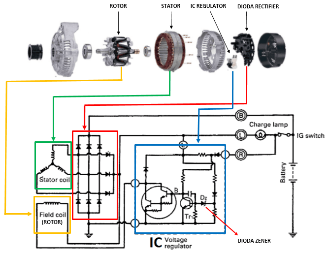
See the images below for a simple representation of an alternator diagram, parts, and function.
From the images above, the main parts of alternator works are :
- Rotor assembly; Rotor assembly will act as a magnet where spinning (moving) inside the stator assembly. The rotor assembly will have magnetic fields (becoming a magnet) when the electric current from the battery flows to its coil through the carbon brush.
- Stator assembly; Stator assembly will act as a coil were connected to the electrical load. The stator assembly will generate electric current when magnetic fields cut its coils.
- IC Regulator (voltage regulator); IC regulator is used to control the alternator output voltage to prevent over-charging and under-charging of the battery. IC regulator regulates the current flowing from the battery to the rotor's assembly.
- Rectifier; Rectifier is used to change the alternating current (AC) generated from the stator assembly into direct current (DC). Rectifiers are commonly made by several diodes.
And other parts of an alternator are pulley, housings, bearings, and a protective cap was working together as an alternator to generate electric current. For more detail about alternator parts and function, you can read the alternator parts and function post that I wrote before.
Read also:- How to check if your alternator is bad?
- #5 Signs of car alternator problems
- What makes an alternator go bad?
II. How an alternator works
After we know the principle works of an alternator and its main parts, now we move to how the alternator work. To better understand how an alternator works, we give important clues for each part based on the electromagnetic work principle.
- Rotor assembly will act as a magnet. The rotor becomes a magnet when the electric current from the battery flows.
- Stator assembly will generate electric current after the rotor magnetic field cuts the coil.
- The rectifier will change the alternating current were generates from the stator assembly into direct current.
- The voltage regulator will regulate the voltage output by controlling the current were flow to the rotor assembly.
Here is how an alternator works
- When the ignition key is ON, the rotor assembly becomes a magnet because the electric current flow from the battery. The rotor is not spinning in this position, so the stator assembly is not generating the electric current.
- When we start the engine and run, the engine will drive the alternator belt to drive the pulley and rotate the rotor assembly.
- As the rotor rotates, the magnetic field in the rotor assembly will cut the stator coil and generate the electric current because of electromagnetic induction.
- The generated electric current is in alternating current (AC) form. Then the rectifier is used to change the alternating current to the direct current so the electric current can be used.
- The electric current will flow to the voltage regulator, so the voltage has a constant value. The most voltage regulator in a car charging system will produce 14,2V-14,5V so it can charge the battery.
- In several voltage regulators, the electric voltage stabilization process uses a Zener diode. When the engine runs, the stator will always generate an electric current. If the current voltage is higher than the Zener diode preferences, it makes the Zener diode become ON.
- Suppose the Zener diode is in the ON position (this position will let the electric current flow). In that case, the current flowing to the rotor assembly will stop immediately. Then, the rotor assembly will lose its magnetic field, and the stator assembly will stop generating electric current.
- Stopped electric current from stator coil will reduce the current voltage to the Zener diode. When the voltage is less than the Zener diode preferences, the Zener diode will be OFF.
- As the Zener diode is OFF, the electric current will flow back from the battery to the rotor assembly. It also makes the stator coil generate the electric current again.
- That is the process of stabilizing the voltage that occurs inside the alternator. This process will work over and over again as long as the engine is still running.

